Synchronizing the photos of two StereoPi boards
You may ask "Why do I need to use a bunch of the StereoPi?"
Well, we got a set of requests from our customers, who need to take a lot of images at once. One of the most popular use cases is the creation of animated "3D" GIFs. These images are created using a set of images (usually 4). In our article we are describing all processes, starting from capturing files and up to creating MP4 video files. So you can post it as a video, or use a video->gif converter to get an animated image.
The second popular use case is a 3D reconstruction, using a set of cameras. For example, through the use of Multi-View 3D Digital Image Correlation (Multi-DIC), a technique recently published by Dr Dana Solav and Dr Kevin Moerman.
DIC allows the researchers to capture both the 3D shape and the 3D deformation of the objects imaged. Their application is imaging of the lower limb with the aim of automated design of prosthetic devices.
Their initial work featured a circular array of 12 Raspberry pi systems with cameras. However, true synchronous imaging and triggering of the separate cameras proved very challenging, and the lack of proper triggering is limiting the application to relatively slow movements.
Since StereoPi systems can naturally acquire images simultaneously from two cameras Dr Kevin Moerman is now exploring the use of this simple StereoPi setup for 2-camera DIC:
Through the use of the StereoPi system they can now achieve synchronised imaging and simplify their set-up significantly. The two camera DIC setup will enable low cost deformation and strain imaging, e.g. for imaging tensile testing of materials.
You can find more details in Dr Kevin Moerman's post on our forum here.
In the future they aim to use a circular set-up featuring multiple StereoPi systems to achieve full 360 degree shape and deformation imaging, and will require simultaneous triggering.
Let's go!
In this article, the goal is to synchronize the photos taken by two StereoPi boards in order to have four viewpoints of the same scene. For this purpose, we will implement different mechanisms to react to an external signal with low latency and moreover low jitter. In bonus, the chosen solution is very versatile and can be used out of the box for many applications. For example, you can use it to synchronize more than two boards, use a button to shoot with high reactivity, command the trigger with hand-made electronics (e.g. sensor on an Arduino), and so on.
Principle
The principle can be separated in two parts: electronics and software. The first will ensure that the two boards can exchange the simple trigger signal at very high speed, and the second will execute the action.
From electronics to software
There are a lot of ways to synchronize the boards. For example, we could have used the Ethernet network to transfer the order, but this channel has unpredictable timings by nature. Of course, we could have got around by synchronizing their clock quite accurately with NTP (Network Time Protocol) and use it as a common base for the two software, but… Fortunately there is something far better and easier on the StereoPi.
Actually, we have access to the GPIOs of the processor. This is a low-level peripheral which can be used to communicate with digital electronic signals. Moreover, these GPIOs have special hardware parts that allow to detect when the signal changes on their pin, and this change can optionally trigger special hardware feature named interrupt that we will explain hereafter.
An interrupt is a special mechanism in a processor that literally interrupts the current operations by switching to a different part of the code, called an interrupt service routine – which is under the responsibility of the kernel when the processor runs an operating system. After this routine ends, the execution of the previous code resumes. Of course, there are many subtleties to make it work, but those are for the engineers designing them. Generally, the interrupts are used in peripherals to inform the operating system of an event, so that this one does not have to spend precious time to poll the peripheral uselessly, and as a side effect it helps to react faster.
In our case, the interrupt routine is of course serviced immediately by the Linux kernel which handles the low-level management of it and delegates the actual work to its GPIO driver. Our software will communicate with this driver, but the details will be given in the next section.
To benefit from this mechanism, we can use a GPIO as output in one board and a GPIO in interrupt mode in the second one – without forgetting to connect the GND of all boards together, which is almost always required.
However, we can be cleverer: we will use an open-drain configuration. This term comes from the transistor world, but basically it just means that the wire will never be driven directly at HIGH state. Instead all parts connected to this wire will drive it LOW when needed and the HIGH level will recover thanks to pull-up resistors when all parts let the drain of their output transistor open, which means that they do not force any level at all. In our case, the pull-up resistors will be replaced by internal pull-up of the processor to limit the requirement of external components. This configuration is often used in real designs and it allows multiple parts to have the same action on the same wire without conflict, but it can cause big damages if something else than GND were set on the wire by error.
This trick will actually allow to connect more than two boards together. It will also let you connect a button between the wire and the GND to trigger the photo manually, and this button can be used concurrently with a software trigger without problem – which on the other hand needs another dedicated GPIO. Another important aspect of this choice is that the two boards are in a symmetrical situation which helps to have a similar time of reaction.
We will thus use two GPIOs in each StereoPi: GPIO3 to react on the falling edge, and GPIO4 to drive LOW if we want to shoot from software.
After these explanations, the wiring is quite obvious:
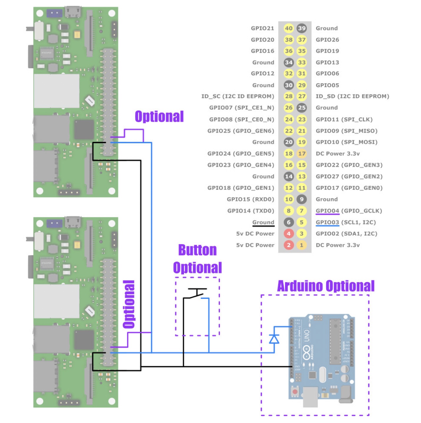
Legend: Wiring of the two StereoPi, including optional Arduino or button as examples. The wire on GPIO4 is also optional and useful only if you want to initiate the photo from a program running on the associated StereoPi
Software tricks
The critical part of the software is the program that communicates with the GPIO driver and takes the photo. This part will be written in C language, although it is a bit complex, in order to have a better control on the timing, and in particular avoid uncontrolled memory allocations that can arise in higher level programming languages such as python, which would introduce undesirable and asymmetrical jitter. Our program will use some pretty advanced notions, but don’t worry, we will provide some explanations and the solution can be used without understanding every single line of code.
There are several other tricks here too. One of them is that we will use raspistill in a special mode in which it can wait for a software interrupt to take its photo. A software interrupt is technically different from hardware ones, but serve the same purpose: being notified of an event without spending useless energy to check if it happens. It is also known as a signal.
Classical software interrupts are SIGFPE (Floating Point Exception, sent by the kernel when there is a division by zero for example), SIGSEGV (Segmentation fault, sent by the kernel when an unauthorized memory address is accessed), SIGKILL (used to kill a program), and so on. There are also SIGUSR1 and SIGUSR2 available to programmers and the first is used by raspistill to take a photo. To send a signal, we have to use the kill system function, whose name is certainly a bit confusing the first time we see it.
To communicate with the GPIO driver, we will use its sysfs interface. This is a virtual filesystem generally mounted in the /sys/ directory in Linux where the files actually represent entry points in the drivers. For example, by writing to a specific file in this sysfs tree, we can ask to set the chosen GPIO in output or input mode. To get the interrupt event, we have to call a special system function on a specific file, which will block the program (it will not consume CPU) until the interrupt arrive: the program will be woken up by the interrupt signal.
Finally, a last trick will be to place our piece of software in the round-robin scheduler of Linux, which is a scheduler with very high priority. The downside is that our program has to be written carefully as any unwanted busy loop may starve the rest of the system of processor time, even if this statement has to be mitigated because actually there are some mechanisms enabled by default in the Linux kernel to reduce the impact of this problematic situation and because you can starve only one core at the time per thread.
Software
Code, compilation, execution
You can download this code as a file here.
Here is the actual code:
...

int raspistill_pid = -1;

int set_rr_scheduler(void) {
	struct sched_param param;
	param.sched_priority = 1;
	return pthread_setschedparam(pthread_self(), SCHED_RR, ¶m);
}

int start_raspistill(void) {
	int pid = fork();

	if (pid < 0) {
		return pid;

	} else if (pid == 0) {
		close(STDIN_FILENO);
		char pattern[50];
		snprintf(pattern, sizeof(pattern), "shot_%ld_%%d.jpg", time(NULL));
		printf("Files pattern: %s\n", pattern);
		execl("/usr/bin/raspistill", "/usr/bin/raspistill", "-s", "-t", "0", "-3d", "sbs", "-vf", "-hf", "-w", "5184", "-h", "1944", "-o", pattern, NULL);
		perror("raspistill");
		exit(EXIT_FAILURE);
	}

	return pid;
}

int setup_gpio(void) {
	int fd, res;

	// Export
	fd = open("/sys/class/gpio/export", O_WRONLY);
	if (fd < 0) return fd;
	res = write(fd, "3", 1);
	if (res < 0) return res;
	close(fd);

	// Set input
	fd = open("/sys/class/gpio/gpio3/direction", O_WRONLY);
	if (fd < 0) return fd;
	res = write(fd, "in", 2);
	if (res < 0) return res;
	close(fd);


	// Set pull-up thanks to raspi-gpio
	system("raspi-gpio set 3 pu");

	// Set falling edge
	fd = open("/sys/class/gpio/gpio3/edge", O_WRONLY);
	if (fd < 0) return fd;
	res = write(fd, "falling", 7);
	if (res < 0) return res;
	close(fd);

	return open("/sys/class/gpio/gpio3/value", O_RDONLY);
}

void release_all(void) {
	int fd = open("/sys/class/gpio/unexport", O_WRONLY);
	if (fd >= 0) {
		write(fd, "3", 1);
		close(fd);
	}
	if (raspistill_pid >= 0)
		kill(raspistill_pid, SIGTERM);
	wait(0);
}

void sighandler(int signal) {
	printf("Signal %d received, exit.", signal);
	exit(EXIT_SUCCESS);
}

int main(void) {
	// Set in the round-robin scheduler of Linux
	int setsched = set_rr_scheduler();
	if (setsched != 0) {
		fprintf(stderr, "Unable to change to the round-robin scheduler: %s\n", strerror(errno));
		fprintf(stderr, "Continueing with regular scheduler\n");
	}

	// Start raspistill
	raspistill_pid = start_raspistill();
	sleep(1);
	if (raspistill_pid < 0 || kill(raspistill_pid, 0) < 0) {
		fprintf(stderr, "Unable to start raspistill: %s\n", strerror(errno));
		exit(EXIT_FAILURE);
	}

	// Guards
	atexit(&release_all);
	signal(SIGTERM, sighandler);
	signal(SIGINT, sighandler);

	// Setup GPIO
	int gpio = setup_gpio();
	if (gpio < 0) {
		fprintf(stderr, "Unable to setup GPIO: %s\n", strerror(errno));
		exit(EXIT_FAILURE);
	}

	// Wait for edge and send signal
	char dummy[512];
	struct pollfd pollfds[2];
	read(gpio, dummy, sizeof(dummy));
	while (1) {
		memset(&pollfds, 0, sizeof(pollfds));
		pollfds[0].fd = gpio;
		pollfds[0].events = POLLPRI;
		pollfds[1].fd = STDIN_FILENO;
		pollfds[1].events = POLLIN | POLLPRI;
		int pollres = poll(pollfds, 2, 500);
		if (pollres > 0) {
			if (pollfds[0].revents) {
				kill(raspistill_pid, SIGUSR1);
				printf("Photo GPIO!\n");
				read(gpio, dummy, sizeof(dummy));
				usleep(500*1000);
			}
			if (pollfds[1].revents) {
				int res = read(STDIN_FILENO, dummy, sizeof(dummy));
				if (res <= 0) break;
				if (res == 2 && dummy[0] == 'q') break;
				if (res == 2 && dummy[0] == 'p') {
					kill(raspistill_pid, SIGUSR1);
					printf("Photo STDIN!\n");
				}
			}
		}
	}

	close(gpio);
	release_all();

	return EXIT_SUCCESS;
}
Of course, the cameras should not be used by another program for this one to work correctly. Let’s try it on the OpenCV image (see wiki) which has a compiler already installed and no program that uses the camera by default.
To compile this program, simply type:
gcc -o stereopi_sync stereopi_sync.c -pthread
After the compilation succeeded, you can run it with:
sudo ./stereopi_sync
The photo can be taken either with the GPIO or by pressing [p][enter] in the terminal. [q][enter], Ctrl-D (close standard input) or Ctrl-C (send interrupt signal) exit the program. Of course, you have to run the program on each StereoPi and connect the wires to benefit from the synchronization mechanism.
The call to raspistill is hardcoded on line 32. If you want to change its arguments, keep in mind that the first three ("/usr/bin/raspistill", "/usr/bin/raspistill", "-s") and the last (NULL) are mandatory here. If you do not need more explanations, you can skip the next section.
Explanations
The general structure is like this: First we have the traditional includes in the C language to get the prototypes of the system function that we use. On line 13 we have a global variable which will store the process ID of raspistill to be able to send a signal to it. A function set_rr_scheduler sets the program in the high priority round-robin scheduler, a function start_raspistill will start raspistill so that we can get its process ID, a function setup_gpio will configure the GPIO system and return a file-descriptor to the opened GPIO, a function release_all will release the GPIO and stop raspistill, a function sighandler will handle software signals and finally a function main which is the entry point.
set_rr_scheduler is simply a wrapper around the pthread_setschedparam system function to call it with the right parameters. For more information, as for the other system functions listed afterwards, please refer to the so called “manual”, a documentation widely available which details what the system functions do, what are the arguments, the return value, the errors, and so on.
start_raspistill is a little more tricky. We need to get the process ID of raspistill and thus we have to launch it ourself the hard way. We first call fork which will duplicate the current program (literally): one instance will continue with 0 in the pid variable (known as the child) and the other will have the process ID of the new (duplicated) process. This one will simply return the process ID and continue the program, but for the child, it is an other story… First, we close the standard input to be sure to not receive the typed text. Then, we forge a pattern for file names starting with shot_ followed by a number based on time (this avoids name conflicts if you stop and launch again as raspistill restarts its sequence at 0) followed by _%d which is the format expected by raspistill for a sequence of images (there are two % in the code because it is formatted by snprintf for which this character has a special meaning). Finally we launch raspistill with one of the exec* system commands where we pass its parameters (notice the “-s” which set raspistill to wait for the USR1 signal), which will literally replace the current process by the new one. If all goes well, the remaining code is never executed. If there is an error while executing execl, we handle the error and exit.
setup_gpio is more classical. We deal with the GPIO driver through its sysfs interface the same way we would deal with classical files by writing the configuration into them. We first export GPIO3, set it as input, call raspi-gpio to set the pull-up, configure the falling edge detection, and return a file descriptor on the pseudo file containing the value that will be used later.
release_all un-exports the GPIO, sends a TERM signal to raspistill and wait for all children to terminate. This last operation avoid zombies programs in the system.
sighandler simply exits the program.
And finally, the main function glues all together. We first set the program in the round-robin scheduler. Then we launch raspistill which will inherit from the scheduling policy and thus also be in this high priority scheduler. After one second, we check if it is still alive with the kill function with 0 signal (this is a special value that only checks if it is possible to contact the process ID). Then we set guards to exit nicely at the end of the program or when the TERM or INTERRUPT signals are received. In particular, it will call the release_all function. Then we setup the GPIO as described earlier.
The core comes just after and uses other advanced functions. First, we read the GPIO value so that the driver clears any pending interrupt. Then we loop on the poll function. Again contrary to what its name suggests, this function will wait for some events (configured in its parameters) without consuming CPU time. Here we ask for urgent data to be read on the GPIO (emitted on the interrupt) and normal and urgent data to be read on standard input (emitted when you type [enter] in the terminal). When the poll function is woken up, it returns which events were captured and we test them. If we got a GPIO event, we send the USR1 signal to raspistill, read the GPIO to clear the event, and wait 500ms to avoid getting the event again on the possible ripples of a mechanical contact. If we got standard input event, we read the value and decide what to do depending on this value, including sending the USR1 signal to raspistill if the content is “p\n”. After the loop, we close the program nicely.
That’s it. It is a bit complex and uses advanced system calls, but should minimize jitter in the shooting process to have a pretty good synchronization between the two StereoPi boards.
How to shoot
Shutter button
The easiest way to shoot with this system is certainly to add a button between the synchronization wire and the GND. When you press the button, the synchronization wire is driven LOW because of your short and the software detects it.
You can add this button without any additional electronic because the software will ignore the undesired edges that will be generated by the imperfection of the mechanical contact. It does this thanks to a neutralization time during which it do not wait for an other edge in order to avoid to trigger on a ripple of the last contact. However, it can sometimes trigger on a ripple of the release if you are not fast enough.
Software trigger
This way uses the second GPIO connected to the synchronization wire. The important consideration is that we want to drive LOW to shoot, but stop driving it afterwards. In particular, we SHOULD NOT set a HIGH signal which could cause damages. Instead, we have to change the direction to input which will stop to drive the line. It looks quite unusual, but it is necessary because of the chosen open-drain configuration.
Since there are no constraints on this program, we can do it in any language we want. For example, this is how to do it with python and its Rpi.GPIO library:
#!/usr/bin/env python3

# Import libraries
import RPi.GPIO as GPIO

# Config
pin_notation = GPIO.BCM
trigger_pin = 4

# Setup
GPIO.setmode(pin_notation)
GPIO.setup(trigger_pin, GPIO.IN)

# Trigger pin
GPIO.setup(trigger_pin, GPIO.OUT)
GPIO.output(trigger_pin, GPIO.LOW)
GPIO.setup(trigger_pin, GPIO.IN)

# Cleanup at exit
GPIO.cleanup()
Of course, you can adapt this code to suite your needs.
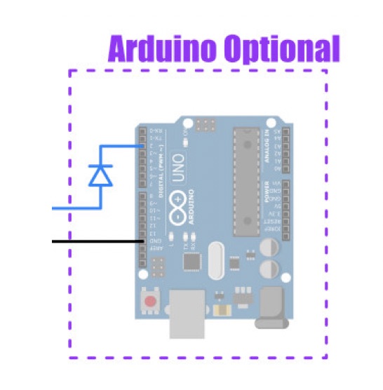
Arduino
As we cited it in the introduction, here is a way to take a photo with this system using an Arduino connected to the synchronization wire. The pins are D2 and GND in the following example. Because the classical Arduino operates in 5V, we added a diode to protect the StereoPi in case of error (e.g. wrong sketch started by accident). Be sure to connect it in the right direction!
The same explanation as the previous case (Software trigger) applies. For example, this program asks for a photo every 5 seconds:
// Config
int trigger_pin = 2;

// Setup
void setup() {
 digitalWrite(trigger_pin, LOW);
 pinMode(trigger_pin, INPUT);
}

void loop() {
 // Trigger pin
 pinMode(trigger_pin, OUTPUT);
 pinMode(trigger_pin, INPUT);

 // Wait 5 seconds
 delay(5000)
}
Of course, you can adapt this code to do more useful work, such as reacting to an external signal. For example, you might react to a shadow on a light sensor, a clap sound, a cut of infrared barrier, a threshold distance measured with ultrasonic sensor and so on.
Tests
To finish, let’s do some tests in the field.
Startup trick
To simplify the usage, the program can be added in the startup scripts, for example in /etc/rc.local, so that it is started without manual intervention. Since there are two independent boards to manage, this is very handy.
However, the application stops when stdin is closed, so we have to create a fake input. For this, we can use the tail utility which prints the content of a file and its -f option which keeps the file opened to display new content when it arrives, and use it on the /dev/null pseudo-file that has no content and never updates.
Assuming that the program is in /home/pi, the line to write in /etc/rc.local is:
cd /home/pi && tail -f /dev/null | ./stereopi_sync &
Important: Do not forget the final ampersand.
Real photos
On the forum, the user pesinasiller suggested to use 4 cameras to create an animated Nimslo-like photograph. This would be a good occasion to test the synchronization.
To create the animation, first align the pairs and crop them the same way. Unlike classical stereophotographs, the effect looks better with a stereoscopic window set in the middle of the scene’s depth (where it would have created severe window violations in stereoscopic view). Then arrange them in the order 1, 2, 3, 4, 3, 2 and loop this pattern a couple of times, like in this list.txt file:
file 'out_0000.jpg'
file 'out_0001.jpg'
file 'out_0002.jpg'
file 'out_0003.jpg'
file 'out_0002.jpg'
file 'out_0001.jpg'
file 'out_0000.jpg'
file 'out_0001.jpg'
file 'out_0002.jpg'
file 'out_0003.jpg'
file 'out_0002.jpg'
file 'out_0001.jpg'
One iteration is sufficient, but multiple times is more pleasant when downloaded and played only once.
Now you can create the animation with ffmpeg:
ffmpeg -f concat -r 6 -i list.txt -vf scale=-2:320 anim.mp4
Note that we resize it on-the-fly. The “-2:320” parameter of the “scale” plugin means that we want a video with a height of 320 pixels and the corresponding width with pair number of columns (required by mp4 format). Other parameters indicate that we will use a “concat” format for the file “list.txt” with a framerate of “6” (fps) and output the result in “anim.mp4”.
To include it in a web page, you can use the video tag with the loop and autoplay attributes:
<video autoplay loop>
<source src="anim.mp4" type="video/mp4">
</video>
Here are some more examples with a 65mm base between each camera:
You can download our mp4 files we used to create these GIFs here:
a1.mp4, a2.mp4, a3.mp4, a4.mp4, a5.mp4, a6.mp4, a7.mp4
Conclusion
We applied a lot of tricks to reduce the jitter on the elements under our control, but it remains some inaccuracies. It can freeze the movement of a running chicken or hunting sparrows in the distance, but really fast movements, such as closer sparrows (they move very fast) or the flapping of insects’ wings, are unfortunately frozen at different moments in the two pairs. The difference is small though. While not perfect, the synchronization is pretty good and actually adequate for a lot of frequent scenes.
What project would you do with this advanced way of using the StereoPi? Let us know in the forum.
Author: Stereomaton